What Is Voltage Drop and Why Does It Matter?
Voltage drop is the reduction in voltage as electrical current flows through a conductor. Every wire has resistance, and the longer the wire and the more current it carries, the more voltage is lost between the source and the load. The result: equipment at the end of the run doesn't get the voltage it needs to operate properly.
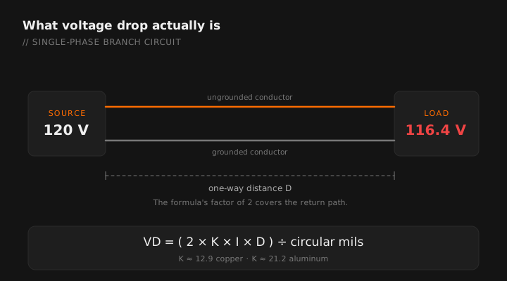
The NEC addresses voltage drop in informational notes rather than mandatory requirements, but inspectors and engineers treat the recommendations seriously. Poor voltage drop means flickering lights, overheating motors, tripped breakers, and unhappy customers.
The Voltage Drop Formula
For single-phase circuits, the standard voltage drop formula is:
Where:
- VD = Voltage drop (in volts)
- K = Resistivity constant (12.9 for copper, 21.2 for aluminum)
- I = Current in amperes (load current)
- D = One-way distance in feet (source to load)
- CM = Circular mil area of the conductor
The app's voltage drop calculator takes the same four inputs and answers instantly.
The "2" in the formula accounts for the round-trip distance — current flows out on the hot conductor and returns on the neutral.
For three-phase circuits, replace the 2 with 1.732 (the square root of 3):
Step-by-Step: How to Calculate
Step 1: Gather Your Values
You need four pieces of information: the conductor material (copper or aluminum), the load current in amps, the one-way distance from the panel to the load in feet, and the wire size you're planning to use (which gives you the circular mil area).
Step 2: Look Up Circular Mils
Common circular mil values for copper conductors:
- #14 AWG — 4,110 CM
- #12 AWG — 6,530 CM
- #10 AWG — 10,380 CM
- #8 AWG — 16,510 CM
- #6 AWG — 26,240 CM
- #4 AWG — 41,740 CM
- #2 AWG — 66,360 CM
- #1/0 AWG — 105,600 CM
- #2/0 AWG — 133,100 CM
Step 3: Plug In and Calculate
Scenario: 20A load on #12 AWG copper, 150-foot run, 120V single-phase.
VD = (2 × 12.9 × 20 × 150) / 6,530
VD = 77,400 / 6,530 = 11.85 volts
Percentage: 11.85 / 120 = 9.9% — This exceeds the 3% recommendation significantly. You need to upsize the conductor.
With #8 AWG: (2 × 12.9 × 20 × 150) / 16,510 = 4.69V (3.9%) — Still over 3%. Consider #6 AWG or reducing the circuit length.
Scenario: 100A load on #1/0 AWG copper, 200-foot run, 208V three-phase.
VD = (1.732 × 12.9 × 100 × 200) / 105,600
VD = 446,976 / 105,600 = 4.23 volts
Percentage: 4.23 / 208 = 2.03% — Under the 3% recommendation. This wire size works.
Step 4: Check Against NEC Recommendations
The NEC recommends no more than 3% voltage drop on the branch circuit and no more than 5% total (feeder + branch circuit combined). These aren't hard code requirements — they're informational notes — but most inspectors and engineers treat them as the standard.
Common Mistakes
- Forgetting the round-trip: The "2" in the formula is there for a reason. Current travels out and back.
- Using the breaker size instead of actual load: If you have a 20A breaker but the actual load is 16A, use 16A for a more accurate calculation.
- Ignoring temperature: The K factor changes at higher temperatures. 12.9 for copper is at 75°C. At higher temperatures, resistance increases.
- Not accounting for the feeder: Your branch circuit might be fine at 2.5%, but if the feeder already drops 3%, you're over 5% total.
When to Upsize Conductors
If your calculation shows excessive voltage drop, you have two options: upsize the conductor (use a larger wire gauge with more circular mils) or shorten the run (relocate the panel or sub-panel closer to the load). In practice, upsizing the conductor is usually the more practical solution.
On long commercial runs, it's common to go up one or two wire sizes specifically for voltage drop — even when the ampacity of the smaller conductor would be sufficient for the load.
Enter length, load and conductor size. Get the drop and the next size up. Free tier.
GET THE FIELD PACK
Two printables: the 22-point rough-in checklist, and branded panel schedules in 24, 30 and 42 circuit that print at 4 by 5 inches and slide straight into a panel sleeve. Enter your email and the downloads open right away.
You're set. Both are below.
Your address comes straight to Jason. No list rental, no spam, unsubscribe any time.