Conduit fill is a space problem, not a heat problem. The question is whether the conductors physically fit inside the raceway with enough room to be pulled without damaging the insulation. It is answered with cross-sectional area, and the tables live in Chapter 9 of the code book.
People confuse it with derating constantly. They are unrelated. You can pass fill comfortably and still be required to reduce conductor ampacity, and you can fail fill with only three conductors that need no derating at all.
The three fill percentages
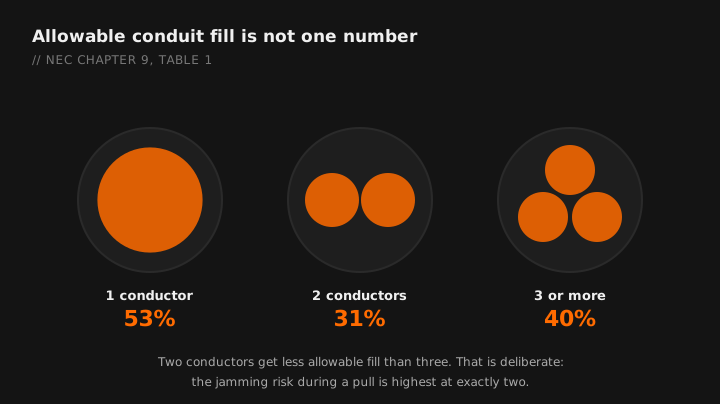
From Chapter 9, Table 1. This is the part that surprises people:
| Number of conductors | Maximum fill |
|---|---|
| 1 conductor | 53% |
| 2 conductors | 31% |
| 3 or more conductors | 40% |
| Nipples not over 24 inches | 60% |
Two conductors get less allowable fill than three. That is not a typo and it is not arbitrary. Two round conductors in a round raceway leave awkward, unusable geometry in the corners, and the jamming risk during a pull is highest with exactly two. Three or more pack better.
The 60 percent allowance for nipples under 24 inches is genuinely useful and routinely forgotten. Short raceways between adjacent enclosures also escape the ampacity adjustment factors entirely.
How the calculation works
Three steps, three tables.
- Table 4 gives you the internal area of each raceway type and trade size, along with the pre-calculated 53, 31 and 40 percent columns. Use the column that matches your conductor count and the row that matches your raceway type. EMT, IMC, rigid, PVC Schedule 40 and PVC Schedule 80 all have different internal areas at the same trade size.
- Table 5 gives you the cross-sectional area of each conductor, by insulation type and size. This is where insulation matters as much as gauge.
- Multiply and compare. Total conductor area must not exceed the allowable raceway area.
Pick conduit type, size and conductor, and the app returns the count and the fill percentage.
The tables you need most
EMT internal area
| Trade size | Total area | 40% (3+ conductors) | 31% (2) | 53% (1) |
|---|---|---|---|---|
| ½ in | 0.304 sq in | 0.122 | 0.094 | 0.161 |
| ¾ in | 0.533 sq in | 0.213 | 0.165 | 0.283 |
| 1 in | 0.864 sq in | 0.346 | 0.268 | 0.458 |
| 1¼ in | 1.496 sq in | 0.598 | 0.464 | 0.793 |
| 1½ in | 2.036 sq in | 0.814 | 0.631 | 1.079 |
| 2 in | 3.356 sq in | 1.342 | 1.040 | 1.778 |
THHN and THWN-2 conductor area
| Size | Approximate area |
|---|---|
| 14 AWG | 0.0097 sq in |
| 12 AWG | 0.0133 sq in |
| 10 AWG | 0.0211 sq in |
| 8 AWG | 0.0366 sq in |
| 6 AWG | 0.0507 sq in |
| 4 AWG | 0.0824 sq in |
| 2 AWG | 0.1158 sq in |
| 1/0 | 0.1855 sq in |
| 2/0 | 0.2223 sq in |
| 3/0 | 0.2679 sq in |
| 4/0 | 0.3237 sq in |
Quick reference: THHN in EMT
Same-size conductors, three or more, so the 40 percent column. These match Annex C, which is the shortcut table for exactly this case.
| EMT size | 14 AWG | 12 AWG | 10 AWG | 8 AWG | 6 AWG |
|---|---|---|---|---|---|
| ½ in | 12 | 9 | 5 | 3 | 2 |
| ¾ in | 22 | 16 | 10 | 6 | 4 |
| 1 in | 35 | 26 | 16 | 9 | 7 |
| 1¼ in | 61 | 45 | 28 | 16 | 12 |
| 1½ in | 84 | 61 | 38 | 22 | 16 |
| 2 in | 138 | 101 | 63 | 36 | 26 |
Annex C only works when every conductor is the same size and the same insulation. The moment you mix, you are back to Tables 4 and 5 and doing the arithmetic. That is most real jobs, since your ground is usually a different size than your phases.
Worked example: mixed sizes
Conductor area:
3 × 0.0507 = 0.1521 sq in
1 × 0.0211 = 0.0211 sq in
Total = 0.1732 sq in
Four conductors, so the 40 percent column.
¾ inch EMT allows 0.213 sq in at 40 percent. Our 0.1732 fits.
Answer: ¾ inch EMT. Fill works out to 0.1732 ÷ 0.533 = 32.5 percent, comfortably inside the limit.
Check ½ inch for completeness: it allows 0.122 sq in, and we need 0.1732. It does not fit.
Worked example: exactly two conductors
Conductor area: 2 × 0.0824 = 0.1648 sq in
Two conductors, so the 31 percent column.
¾ inch EMT allows 0.165 sq in at 31 percent. Our 0.1648 fits by four ten-thousandths of a square inch.
Answer: ¾ inch EMT, barely. If you had used the 40 percent figure by mistake you would have thought you had 29 percent of headroom you do not actually have.
That example is the argument for reading the conductor count column carefully. Two is the strict case.
Things that change the answer
Insulation type
XHHW-2 and THHN of the same AWG have different outside diameters. So do RHH, USE and the various compact aluminum constructions. Same gauge, different area, different count. Look up the actual insulation you are pulling.
Raceway type
At the same trade size, PVC Schedule 80 has noticeably less internal area than Schedule 40, which has less than EMT in some sizes. Rigid and IMC differ from each other. Never carry an EMT count over to another raceway type.
Conductors of different sizes
The tables assume nothing about uniformity, so mixed sizes are fine, you just have to sum the areas individually rather than multiplying one number.
Jamming
Not a code requirement, a physics one. Pulling three conductors through a raceway whose inside diameter is close to three times the conductor diameter risks the conductors wedging in a bend. If your ratio of raceway ID to conductor OD lands near 2.8 to 3.2, consider upsizing even though fill passes.
Fill is not derating
Worth repeating, because it costs people money.
Fill asks whether the conductors physically fit. Ampacity adjustment asks whether they can shed heat. Once more than three current-carrying conductors share a raceway, you reduce ampacity per the adjustment factors regardless of how much room is left in the pipe. See the ampacity guide for that calculation. Passing fill is not a defense on an ampacity citation.
Practical sizing habits
- Leave room for the future. Fill to 40 percent and the raceway is full forever. Upsizing one trade size at rough-in costs a few dollars and buys the next circuit.
- Count the ground. Every conductor in the pipe counts, insulated or bare.
- Use the nipple allowance. Short raceways between enclosures get 60 percent and no ampacity adjustment. That is a real break.
- Check bends before fill. The 360 degree limit between pull points will stop a pull that fill permits. See the bending cheat sheet.
Every raceway type and insulation in the app, offline. Free tier.
GET THE FIELD PACK
Two printables: the 22-point rough-in checklist, and branded panel schedules in 24, 30 and 42 circuit that print at 4 by 5 inches and slide straight into a panel sleeve. Enter your email and the downloads open right away.
You're set. Both are below.
Your address comes straight to Jason. No list rental, no spam, unsubscribe any time.