The ampacity table is the most-used table in the code book, and it is also the one people most often use wrong. Not because the numbers are hard to read, but because the number you read off the table is almost never the number you are allowed to use.
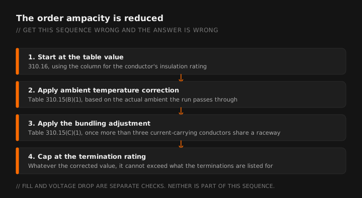
There are three things that happen to a table value before it becomes your actual ampacity: ambient temperature correction, conductor bundling adjustment, and the termination temperature limit. Skip any of them and you have a conductor that is legal on paper and undersized in reality.
The table
These are the ampacities from NEC 310.16 for conductors rated 0 to 2000 volts, not more than three current-carrying conductors in a raceway, at an ambient of 30 degrees C. Values have been stable across recent editions, but verify against the edition your jurisdiction has adopted.
Copper
| Size | 60°C (TW, UF) | 75°C (THW, THWN, XHHW) | 90°C (THHN, THWN-2, XHHW-2) |
|---|---|---|---|
| 14 AWG | 15 | 20 | 25 |
| 12 AWG | 20 | 25 | 30 |
| 10 AWG | 30 | 35 | 40 |
| 8 AWG | 40 | 50 | 55 |
| 6 AWG | 55 | 65 | 75 |
| 4 AWG | 70 | 85 | 95 |
| 3 AWG | 85 | 100 | 115 |
| 2 AWG | 95 | 115 | 130 |
| 1 AWG | 110 | 130 | 145 |
| 1/0 | 125 | 150 | 170 |
| 2/0 | 145 | 175 | 195 |
| 3/0 | 165 | 200 | 225 |
| 4/0 | 195 | 230 | 260 |
Aluminum and copper-clad aluminum
| Size | 60°C | 75°C | 90°C |
|---|---|---|---|
| 12 AWG | 15 | 20 | 25 |
| 10 AWG | 25 | 30 | 35 |
| 8 AWG | 30 | 40 | 45 |
| 6 AWG | 40 | 50 | 55 |
| 4 AWG | 55 | 65 | 75 |
| 2 AWG | 75 | 90 | 100 |
| 1/0 | 100 | 120 | 135 |
| 2/0 | 115 | 135 | 150 |
| 3/0 | 130 | 155 | 175 |
| 4/0 | 150 | 180 | 205 |
Ampacity for copper and aluminum across all three temperature columns, in the app, no signal required.
Step one: the termination rule
This is the rule that overrides everything else, and it is the reason the 90 degree C column exists mostly as a starting point rather than an answer.
Conductor ampacity is limited by the lowest temperature rating of any connected termination, conductor or device. In practice:
- Equipment rated 100 amperes or less, and conductors 14 AWG through 1 AWG, are generally limited to the 60 degree C column unless the equipment is listed and identified for higher.
- Equipment rated over 100 amperes, and conductors larger than 1 AWG, are generally limited to the 75 degree C column.
- Most modern breakers and panelboards are listed for 75 degrees C, which is why the 75 column is where most real work lands.
You are permitted to begin from the 90 degree C column when applying correction and adjustment factors, because those factors are about the conductor's ability to shed heat along its length. But the final answer, after all the math, still cannot exceed the termination-limited value.
Read the equipment, not the internet. The termination rating is on the equipment label or in the listing. A 90 degree C conductor into a 75 degree C lug is a 75 degree C connection. The weakest link sets the limit.
Step two: ambient temperature correction
The table assumes 30 degrees C, which is 86 degrees F. Run conductors through an attic in July and that assumption is fiction. Correction factors from Table 310.15(B)(1) reduce the ampacity accordingly.
| Ambient | 60°C conductor | 75°C conductor | 90°C conductor |
|---|---|---|---|
| 21 to 25°C (70 to 77°F) | 1.08 | 1.05 | 1.04 |
| 26 to 30°C (79 to 86°F) | 1.00 | 1.00 | 1.00 |
| 31 to 35°C (88 to 95°F) | 0.91 | 0.94 | 0.96 |
| 36 to 40°C (97 to 104°F) | 0.82 | 0.88 | 0.91 |
| 41 to 45°C (106 to 113°F) | 0.71 | 0.82 | 0.87 |
| 46 to 50°C (115 to 122°F) | 0.58 | 0.75 | 0.82 |
| 51 to 55°C (124 to 131°F) | 0.41 | 0.67 | 0.76 |
Notice how much better the 90 degree C conductor holds up as ambient climbs. That is the real reason to start from the 90 column: not to get a bigger final number, but to lose less to correction.
Step three: bundling adjustment
Once more than three current-carrying conductors share a raceway or cable, they cannot shed heat as well and ampacity is reduced again. From Table 310.15(C)(1):
| Current-carrying conductors | Percent of table value |
|---|---|
| 4 to 6 | 80% |
| 7 to 9 | 70% |
| 10 to 20 | 50% |
| 21 to 30 | 45% |
| 31 to 40 | 40% |
| 41 and above | 35% |
What counts as current-carrying is its own small subject. A neutral that carries only the unbalanced current of a multiwire branch circuit generally is not counted. A neutral on a circuit supplying substantial nonlinear load generally is. Equipment grounding conductors are never counted.
Raceways not exceeding 24 inches in length are exempt from the adjustment factors entirely.
Putting it together
Six current-carrying 10 AWG THHN copper conductors in EMT through an attic space at 45 degrees C. Terminations rated 75 degrees C. What is the usable ampacity?
Start: 10 AWG copper at 90°C = 40 amps
Ambient correction at 41 to 45°C for a 90°C conductor = 0.87
40 × 0.87 = 34.8 amps
Bundling adjustment for 6 current-carrying conductors = 0.80
34.8 × 0.80 = 27.8 amps
Termination limit: 10 AWG at 75°C = 35 amps. Our corrected value of 27.8 is below that, so the corrections govern.
Usable ampacity: 27.8 amps. The small conductor rule caps 10 AWG overcurrent protection at 30 amps anyway, and 27.8 is below 30, so this conductor supports a load up to 27.8 amps and would typically land on a 30 amp device only if the calculated load stays under the corrected ampacity and the next-size-up rules are satisfied.
A conductor that reads 40 amps in the table delivers 27.8 in this installation. That gap is the entire reason the corrections exist, and it is what separates an ampacity lookup from an ampacity calculation.
What the table does not tell you
Ampacity is a thermal question: can this conductor carry this current without cooking its insulation. It says nothing about whether the voltage arriving at the far end is usable.
On long runs, voltage drop frequently drives a larger conductor than ampacity alone would require. The two calculations are independent, they are both real, and the larger of the two answers is the one you install. A conductor that passes ampacity and fails voltage drop is a callback waiting to happen.
Fill is a third, separate question. Once you know the conductor size, check that they physically fit using the conduit fill tables.
Quick reference: common circuits
These are the answers people are usually looking for. They assume copper, 75 degree C terminations, three or fewer current-carrying conductors, 30 degree C ambient, and a short enough run that voltage drop is not controlling. Change any of those and the answer changes.
| Circuit | Typical copper conductor | Watch for |
|---|---|---|
| 15 A lighting | 14 AWG | Small conductor rule caps at 15 A |
| 20 A general purpose | 12 AWG | Small conductor rule caps at 20 A |
| 30 A dryer or water heater | 10 AWG | Small conductor rule caps at 30 A |
| 40 A range | 8 AWG | Demand factors apply to the load calc |
| 50 A range or EVSE | 8 AWG at 75°C | Continuous load rule for EVSE |
| 60 A subpanel | 6 AWG | Separate grounds and neutrals downstream |
| 100 A feeder | 3 AWG | Termination rating, then voltage drop |
Treat that table as a sanity check on an answer you calculated, never as a substitute for calculating it.
310.16 plus correction and adjustment factors, offline. Free tier, no card required.
GET THE FIELD PACK
Two printables: the 22-point rough-in checklist, and branded panel schedules in 24, 30 and 42 circuit that print at 4 by 5 inches and slide straight into a panel sleeve. Enter your email and the downloads open right away.
You're set. Both are below.
Your address comes straight to Jason. No list rental, no spam, unsubscribe any time.