Two conductors in a service look similar, get called the same thing in conversation, and are sized from two completely different tables. Mixing them up is the most common grounding error in the trade, and it shows up on exams as reliably as it shows up in panels.
GEC and EGC are different animals
| Grounding electrode conductor | Equipment grounding conductor | |
|---|---|---|
| Job | Connects the system to the earth electrode | Provides a fault return path to the source |
| Runs from | Service or separately derived system to the electrode | With the circuit conductors, to every enclosure and device |
| Sized from | The service-entrance conductors | The overcurrent device rating |
| Table | 250.66 | 250.122 |
| Clears faults? | No | Yes, this is its entire purpose |
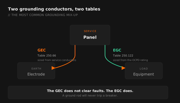
The earth is not a fault clearing path. A ground rod does not trip a breaker. The GEC stabilizes system voltage relative to earth and provides a path for lightning and utility surge events. The conductor that actually clears a ground fault is the EGC, back to the source. People who install a rod and consider the equipment grounded have this backwards.
Table 250.66: sizing the GEC
Size from the largest ungrounded service-entrance conductor, or the equivalent area for parallel conductors.
| Largest service conductor (copper) | Copper GEC | Aluminum GEC |
|---|---|---|
| 2 AWG or smaller | 8 AWG | 6 AWG |
| 1 or 1/0 | 6 AWG | 4 AWG |
| 2/0 or 3/0 | 4 AWG | 2 AWG |
| Over 3/0 through 350 kcmil | 2 AWG | 1/0 |
| Over 350 through 600 kcmil | 1/0 | 3/0 |
| Over 600 through 1,100 kcmil | 2/0 | 4/0 |
| Over 1,100 kcmil | 3/0 | 250 kcmil |
The app keeps 250.66 and 250.122 separate so you do not size off the wrong one.
The caps that override the table
This is the part that makes the whole thing manageable, and it is the part people forget. The required size to a specific electrode type is capped regardless of what the table says.
| Electrode | Cap on required GEC size |
|---|---|
| Rod, pipe or plate electrode | Not required larger than 6 AWG copper |
| Concrete-encased electrode | Not required larger than 4 AWG copper |
| Ground ring | Not required larger than the conductor used for the ring |
Service-entrance conductors are 500 kcmil copper. Electrodes are a concrete-encased electrode plus two driven ground rods.
From Table 250.66: 500 kcmil falls in the "over 350 through 600 kcmil" row, so the table value is 1/0 copper.
To the concrete-encased electrode: capped at 4 AWG copper.
To the ground rods: capped at 6 AWG copper.
Practical result: if your only electrodes are rods and a concrete-encased electrode, you never install the 1/0. The caps govern. The 1/0 would be required only for a run to an electrode with no cap, such as a metal water pipe electrode.
That example is why "just run 1/0 to be safe" is the wrong instinct here. It is expensive, hard to terminate on a rod clamp, and unnecessary.
Table 250.122: sizing the EGC
Size from the rating of the overcurrent device ahead of the circuit, not from the conductor size.
| OCPD rating | Copper EGC | Aluminum EGC |
|---|---|---|
| 15 A | 14 AWG | 12 AWG |
| 20 A | 12 AWG | 10 AWG |
| 60 A | 10 AWG | 8 AWG |
| 100 A | 8 AWG | 6 AWG |
| 200 A | 6 AWG | 4 AWG |
| 300 A | 4 AWG | 2 AWG |
| 400 A | 3 AWG | 1 AWG |
| 600 A | 1 AWG | 2/0 |
| 800 A | 1/0 | 3/0 |
| 1000 A | 2/0 | 4/0 |
Installation rules that fail inspections
Continuity
The GEC must be installed without splice or joint except by specific permitted means: irreversible compression connectors listed for the purpose, exothermic welding, or connection to busbars and certain listed fittings. A wire nut is not one of them.
Protection
A 6 AWG or larger GEC may generally be run along the surface without additional protection where it is not subject to physical damage. Smaller than 6 AWG requires a raceway or armor. Where a ferrous raceway is used, it must be bonded at both ends to the conductor inside it, otherwise the raceway acts as a choke and dramatically increases the impedance of the path.
Aluminum restrictions
Aluminum and copper-clad aluminum grounding conductors are generally not permitted where in direct contact with masonry or earth, or where subject to corrosive conditions. Terminations outdoors have a minimum height requirement above earth. This effectively rules aluminum out for most electrode connections.
Electrode spacing
Where rods are used and a single rod does not meet the resistance requirement, a second is required, and rods in a group must be separated by at least 6 feet. Driving two rods 3 feet apart because that is where the conduit came out is a citation.
The electrode system, briefly
All electrodes present at a building must be bonded together into a single grounding electrode system. That includes:
- A metal underground water pipe in direct contact with earth for the required length
- The metal frame of the building where it qualifies
- A concrete-encased electrode, where present in the foundation
- A ground ring, where installed
- Rod, pipe and plate electrodes
You do not get to pick your favorite. If a qualifying electrode exists at the building, it goes in the system. A metal water pipe electrode additionally requires a supplemental electrode.
Concrete-encased electrode timing. If the footing is being poured, that is your one chance. Coordinate with the concrete contractor before the pour and stub the conductor out where you can reach it later. Retrofitting one is not practical, and the fallback is usually rods.
Quick check before you close the panel
- GEC sized from the service conductors, then capped by electrode type where applicable.
- EGC sized from the overcurrent device, and increased if the phase conductors were upsized.
- No splices in the GEC except by permitted means.
- Ferrous raceway around the GEC bonded at both ends.
- All present electrodes bonded into one system.
- Main bonding jumper installed at the service, and only at the service.
- Downstream panels have grounds and neutrals separated.
That last one and the main bonding jumper are the two that turn up most often on the common violations list, and both belong on your rough-in walkthrough.
GEC and EGC tables in the app, no signal required. Free tier.
GET THE FIELD PACK
Two printables: the 22-point rough-in checklist, and branded panel schedules in 24, 30 and 42 circuit that print at 4 by 5 inches and slide straight into a panel sleeve. Enter your email and the downloads open right away.
You're set. Both are below.
Your address comes straight to Jason. No list rental, no spam, unsubscribe any time.