Transformer work involves two calculations people mix up: how much current flows on each side, and how the thing is protected. The first is arithmetic. The second is Article 450, and it is where the mistakes happen.
The current formulas
A transformer moves power, not current. The kVA stays the same on both sides, so when the voltage goes down the current goes up in proportion. That single sentence explains every number below.
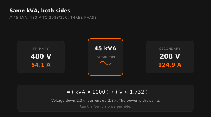
Primary current:
45,000 ÷ (480 × 1.732) = 45,000 ÷ 831.4 = 54.1 amperes
Secondary current:
45,000 ÷ (208 × 1.732) = 45,000 ÷ 360.3 = 124.9 amperes
Same 45 kVA, and the secondary carries roughly 2.3 times the primary current. That ratio is exactly 480 divided by 208.
Common transformer currents
Worth knowing by sight, so you can catch an error before you order anything.
| kVA | 480V 3Ø primary | 208V 3Ø secondary | 240V 1Ø | 120V 1Ø |
|---|---|---|---|---|
| 15 | 18.0 A | 41.6 A | 62.5 A | 125 A |
| 30 | 36.1 A | 83.3 A | 125 A | 250 A |
| 45 | 54.1 A | 124.9 A | 187.5 A | 375 A |
| 75 | 90.2 A | 208.2 A | 312.5 A | 625 A |
| 112.5 | 135.3 A | 312.3 A | 468.8 A | 938 A |
| 150 | 180.4 A | 416.4 A | 625 A | 1250 A |
| 225 | 270.6 A | 624.6 A | 937.5 A | 1875 A |
The app's transformer calculator handles single and three-phase primary and secondary current.
Sizing the conductors
Primary and secondary conductors are sized independently, each from the current on its own side.
- Primary conductors sized for the primary current, at 125 percent where the load is continuous, then checked against termination ratings and voltage drop.
- Secondary conductors sized for the secondary current on the same basis.
- Both checked against ampacity corrections for ambient and bundling, and against conduit fill.
The secondary is usually the surprising one. A 45 kVA transformer sounds small until you see 125 amperes on the secondary and realize you are pulling 1/0 or larger into the distribution panel.
Protection: the part that trips people
Article 450 protects the transformer. The feeder and tap rules protect the conductors. Those are two separate obligations and satisfying one does not satisfy the other.
Primary protection only
For transformers 1000 volts and under, primary-only protection is permitted at a specified percentage of rated primary current, with the permitted percentage increasing as the primary current gets smaller. Where the calculated value does not land on a standard device rating, the next higher standard size is generally permitted within the stated conditions.
Primary and secondary protection
Where secondary protection is provided at the required percentage of secondary current, the primary device is permitted to be set considerably higher. This is the arrangement used on most commercial installations, because it lets the primary device ride through magnetizing inrush without nuisance tripping while the secondary device does the real protecting.
Inrush is why you cannot size a primary device like a branch circuit breaker. Energizing a transformer draws a large magnetizing current for a few cycles. A device sized tightly to the primary full-load current will trip on every energization. That is the reason the permitted percentages look generous.
Secondary conductors are a separate question
The conductors leaving the transformer still need overcurrent protection under the feeder rules. Where the protective device is not immediately at the transformer, the transformer secondary conductor provisions apply, with length limits and ampacity ratios similar in structure to the feeder tap rules. See breaker and OCPD sizing for how those rules are structured.
Separately derived systems
A transformer with no direct electrical connection between primary and secondary windings creates a separately derived system on the secondary, and that carries grounding obligations that people forget until the inspection.
At the secondary you generally need:
- A system bonding jumper connecting the grounded conductor to the equipment grounding conductor and the enclosure, at one point only.
- A grounding electrode conductor to the nearest qualifying electrode, sized from the derived phase conductors. See GEC sizing.
- A supply-side bonding jumper where required.
Grounding and bonding a separately derived system at more than one point creates parallel paths for neutral current, which produces circulating currents on the raceway and equipment grounding conductors. It is a classic cause of unexplained heating and stray voltage complaints.
Delta and wye
The configuration determines what voltages you have available on the secondary.
| Configuration | Available voltages | Typical use |
|---|---|---|
| 480 delta to 208Y/120 | 208 line to line, 120 line to neutral | Most common commercial step-down |
| 480 delta to 240/120 delta | 240 line to line, 120 from the center tap, plus a high leg | Older commercial, mixed motor and lighting |
| 240 delta to 480 wye | Step-up for distribution | Long runs, larger motors |
The high leg. On a 240 volt delta with a center-tapped winding, one phase sits at roughly 208 volts to ground rather than 120. Connecting a 120 volt load to it destroys the equipment instantly. The code requires that conductor be identified, commonly with orange, and placed in a specific position in the panelboard. See three-phase calculations for why that voltage exists.
Practical checks before you order
- Confirm the actual connected load, not the panel rating. Transformers get badly oversized by people sizing to the panel bus.
- Check the K-factor requirement where nonlinear loads dominate. Standard transformers feeding heavy electronic load run hot.
- Verify clearances and ventilation. Dry-type transformers have required clearances from combustible material and ventilation openings that cannot be blocked.
- Check the sound rating if it is going anywhere near occupied space. Transformer hum is a callback that no amount of correct sizing prevents.
- Confirm the secondary distribution before you finalize the kVA. Adding a panel later to an undersized transformer is a full replacement.
kVA, primary amps, secondary amps and conductor sizing. Free tier, works offline.
GET THE FIELD PACK
Two printables: the 22-point rough-in checklist, and branded panel schedules in 24, 30 and 42 circuit that print at 4 by 5 inches and slide straight into a panel sleeve. Enter your email and the downloads open right away.
You're set. Both are below.
Your address comes straight to Jason. No list rental, no spam, unsubscribe any time.