Overcurrent protection looks like one topic and is actually three, with three different sets of rules. Branch circuits and feeders follow one logic. Motors follow another that appears to violate everything you just learned. Transformers follow a third.
Applying branch circuit logic to a motor circuit is probably the single most common sizing error in the trade, and it fails inspections and exams in equal measure. Here is each path, separately.
Path 1: Branch circuits and feeders
The rule for ordinary loads is straightforward: the overcurrent device protects the conductor, so the device rating cannot exceed the conductor ampacity, with a few defined exceptions.
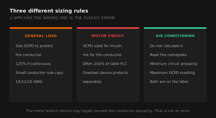
The continuous load rule
Where a load runs for three hours or more, both the overcurrent device and the conductors must be sized for at least 125 percent of that continuous load.
People also state this backwards, as "you can only load a breaker to 80 percent." Same statement, different direction. The 80 percent framing is easier to sanity-check in the field, and 1 divided by 1.25 is 0.8, which is where it comes from.
A commercial lighting circuit draws 16 amperes and runs all day.
16 × 1.25 = 20 amperes minimum.
A 20 ampere device with 12 AWG copper works, but there is zero margin. Any addition to that circuit requires resizing. Most designers would run this on a 20 amp circuit at no more than 16 amps of connected continuous load and stop there.
The small conductor rule
Regardless of what the ampacity table says, overcurrent protection for the small copper conductors is capped:
| Copper conductor | Maximum OCPD | Table ampacity at 90°C |
|---|---|---|
| 14 AWG | 15 A | 25 A |
| 12 AWG | 20 A | 30 A |
| 10 AWG | 30 A | 40 A |
The app carries full-load current tables and the motor multipliers so you are not sizing off a nameplate alone.
This is why a 12 AWG conductor that the table rates at 30 amps still lands on a 20 amp breaker. Specific exceptions exist, notably for motor circuits and certain welder and control applications, which is exactly the point of the next section.
The next size up rule
Where a conductor's ampacity does not correspond to a standard overcurrent device rating, you are generally permitted to go to the next higher standard size. Conditions apply: the device cannot exceed 800 amperes, the conductors cannot be part of a multi-outlet branch circuit supplying receptacles, and the small conductor rule still governs where it applies.
Standard ratings are 15, 20, 25, 30, 35, 40, 45, 50, 60, 70, 80, 90, 100, 110, 125, 150, 175, 200 and up from there.
Path 2: Motors
Motor circuits split protection into two separate jobs handled by two separate devices, and once you see that, the numbers stop looking insane.
| Function | Device | Sized from |
|---|---|---|
| Short circuit and ground fault | Breaker or fuse at the branch circuit | A large multiple of full-load current |
| Overload | Overload relay in the starter, or integral protector | Motor nameplate current |
The branch circuit device has to let the motor start. Inrush on across-the-line starting can be six to eight times running current for a second or two. A device sized to protect the conductor thermally would trip on every start. So the branch device is sized for inrush, and the conductor's thermal protection comes from the overload device instead.
The sizing sequence
- Get full-load current from the NEC motor tables, not from the nameplate. This trips people up constantly. Conductor sizing and branch circuit protection use the table value.
- Size the conductors at 125 percent of that table full-load current for a single continuous-duty motor.
- Size the branch circuit protective device using the percentages for your device type. For an inverse time circuit breaker on a typical squirrel cage motor, the maximum is 250 percent of full-load current. Dual element time-delay fuses run much lower, around 175 percent. Instantaneous trip breakers run much higher.
- Size the overload device from the motor nameplate current, typically at 115 or 125 percent depending on service factor and temperature rise.
Table full-load current: 28 amperes.
Conductors: 28 × 1.25 = 35 amperes minimum ampacity. 8 AWG copper at 75 degrees C is 50 amperes, comfortably adequate; 10 AWG at 35 amperes also satisfies it at the 75 degree C column.
Branch circuit breaker: 28 × 2.50 = 70 amperes. A 70 ampere inverse time breaker is a standard size and is permitted.
Result: a 70 amp breaker protecting a conductor rated 35 to 50 amps. Correct, and it looks wrong to anybody applying branch circuit logic.
Overload: sized separately from the motor nameplate, which is what actually protects that conductor from a sustained overload.
Where the calculated value does not correspond to a standard rating, motor branch circuit protection is generally permitted to go to the next higher standard size, and may be increased further where the motor will not start, subject to hard ceilings in the code. Never increase it because it is tripping without confirming the motor is not actually faulted.
Feeders supplying multiple motors
Sum the full-load currents of all motors, then add 25 percent of the largest motor's full-load current. That addition covers the starting current of the last motor to start while the others run.
Path 3: Transformers
Transformer protection has its own percentages, and there is a distinction people miss: protecting the transformer and protecting the secondary conductors are different requirements.
- Primary protection only is permitted for many transformers at a specified percentage of primary current.
- Where secondary protection is also provided at the required percentage, the primary device may be set considerably higher.
- Secondary conductors still require protection under the feeder and tap rules, which is a separate analysis from transformer protection.
See transformer sizing for the current calculations that feed into this.
Quick decision guide
| Load type | Size the device from | Common trap |
|---|---|---|
| General branch circuit | Conductor ampacity, capped by the small conductor rule | Using the 90°C column as the final answer |
| Continuous load | 125% of the load | Forgetting it also applies to the conductor |
| Motor branch circuit | Percentage of table FLC by device type | Using nameplate instead of table current |
| Motor overload | Nameplate current | Using table current instead of nameplate |
| Motor feeder | Sum of FLC plus 25% of the largest | Omitting the largest-motor addition |
| EVSE | 125% of charger rating | Treating it as noncontinuous |
| Air conditioning | Nameplate maximum overcurrent marking | Calculating it instead of reading the label |
Air conditioning equipment is a special case. The nameplate carries a minimum circuit ampacity and a maximum overcurrent protective device rating, both determined by the manufacturer. Use those numbers. Do not calculate your own; the marked values are what the listing requires and what the inspector will check.
The order of operations
When you are sizing from scratch, run it in this order and you will not double back:
- Determine the load, and decide whether any part of it is continuous.
- Apply the 125 percent factor to the continuous portion.
- Size the conductor for that ampacity, applying ambient correction, bundling adjustment and the termination limit.
- Check voltage drop and upsize if the run demands it.
- Select the overcurrent device against the final conductor ampacity, the small conductor rule, and the next-size-up allowance.
- For motors and air conditioning, throw out steps 4 and 5 and use the motor rules or the nameplate marking instead.
Branch circuits, feeders and motor circuits, with the tables built in. Free tier, offline.
GET THE FIELD PACK
Two printables: the 22-point rough-in checklist, and branded panel schedules in 24, 30 and 42 circuit that print at 4 by 5 inches and slide straight into a panel sleeve. Enter your email and the downloads open right away.
You're set. Both are below.
Your address comes straight to Jason. No list rental, no spam, unsubscribe any time.