Charts are for the tailgate. When you need to know roughly whether a run is going to be a problem before you order wire, a table beats a formula. When you need to commit to a conductor size, go back and run the calculation.
Read this before you use any of the tables
Every voltage drop chart bakes in assumptions, and most charts online do not tell you what theirs are. Here are ours, stated plainly:
- Copper conductors, using a K value of 12.9 ohm circular mils per foot. For aluminum, multiply every length in these tables by roughly 0.61.
- 3 percent target, which is the commonly used branch circuit design figure from the code's informational notes. It is a recommendation, not an enforceable limit, unless your specification or AHJ makes it one.
- One-way distance in feet, from source to load. The formula's factor already accounts for the return path.
- Unity power factor and normal operating temperature. Motor loads with poor power factor will fall short of these numbers.
- Circular mil areas from the code's conductor properties table.
These are maximum lengths for a continuously drawn current at the value shown. A circuit that is rarely loaded to its breaker rating will perform better than the table suggests. A circuit that runs at full load all day will not.
120 volt single-phase, 3 percent
| Conductor | At 10 A | At 12 A | At 15 A | At 20 A |
|---|---|---|---|---|
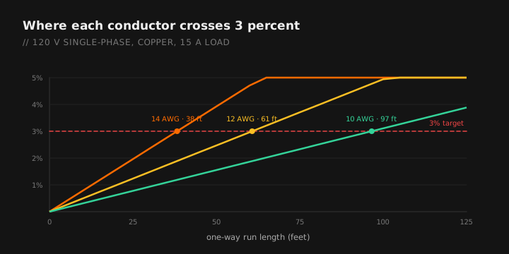
| 14 AWG | 57 ft | 48 ft | 38 ft | — |
| 12 AWG | 91 ft | 76 ft | 61 ft | 46 ft |
| 10 AWG | 145 ft | 121 ft | 97 ft | 72 ft |
| 8 AWG | 230 ft | 192 ft | 154 ft | 115 ft |
For the actual run, the app calculates from your real length, load and conductor.
This is the table that surprises people. A fully loaded 15 amp circuit on 14 AWG crosses 3 percent at 38 feet. Not 38 feet of wall, 38 feet of conductor from the panel. In a two-story house that is a bedroom on the far corner.
240 volt single-phase, 3 percent
| Conductor | Typical load | Max one-way length |
|---|---|---|
| 12 AWG | 20 A | 91 ft |
| 10 AWG | 30 A | 97 ft |
| 8 AWG | 40 A | 115 ft |
| 6 AWG | 50 A | 146 ft |
| 6 AWG | 55 A | 133 ft |
| 4 AWG | 70 A | 166 ft |
| 3 AWG | 85 A | 173 ft |
| 2 AWG | 95 A | 195 ft |
| 1/0 | 125 A | 236 ft |
| 2/0 | 145 A | 256 ft |
| 3/0 | 165 A | 284 ft |
| 4/0 | 195 A | 303 ft |
Doubling the voltage doubles the allowable distance for the same conductor and current, which is why 240 volt circuits reach so much farther than 120 volt circuits.
208 volt three-phase, 3 percent
| Conductor | Load | Max one-way length |
|---|---|---|
| 10 AWG | 30 A | 97 ft |
| 8 AWG | 40 A | 115 ft |
| 6 AWG | 55 A | 133 ft |
| 4 AWG | 70 A | 167 ft |
| 2 AWG | 95 A | 195 ft |
| 1/0 | 125 A | 236 ft |
| 4/0 | 195 A | 303 ft |
480 volt three-phase, 3 percent
| Conductor | Load | Max one-way length |
|---|---|---|
| 8 AWG | 40 A | 266 ft |
| 6 AWG | 55 A | 307 ft |
| 4 AWG | 70 A | 384 ft |
| 2 AWG | 95 A | 450 ft |
| 1/0 | 125 A | 544 ft |
| 4/0 | 195 A | 699 ft |
This is the case for distributing at 480 and stepping down locally rather than running 208 across a large site. Same conductor, same current, more than double the reach. See transformer sizing for the step-down side of that decision.
Adjusting the tables
| If you want | Do this to the table length |
|---|---|
| Aluminum instead of copper | Multiply by 0.61 |
| A 5 percent target instead of 3 | Multiply by 1.67 |
| A 2 percent target | Multiply by 0.67 |
| Half the load shown | Multiply by 2 |
| Double the load shown | Multiply by 0.5 |
Length, load and target percentage all scale linearly, which is why these adjustments are simple multiplication. Conductor size does not scale linearly, because circular mils do not double with each AWG step.
What each conductor step buys you
Going up one size increases circular mils by roughly 26 percent, so it buys roughly 26 percent more distance. Going up two sizes buys about 59 percent. That is worth knowing when you are deciding between upsizing and finding a shorter route.
| From | To | Distance gain |
|---|---|---|
| 14 AWG | 12 AWG | +59% |
| 12 AWG | 10 AWG | +59% |
| 10 AWG | 8 AWG | +59% |
| 8 AWG | 6 AWG | +59% |
| 6 AWG | 4 AWG | +59% |
| 4 AWG | 2 AWG | +59% |
The AWG system is logarithmic, so every two-gauge step is about a 59 percent increase in area. That consistency makes it easy to estimate in your head: two sizes up buys roughly half again the distance.
Where voltage drop actually bites
- Detached garages and outbuildings. The single most common place a residential circuit fails on drop rather than ampacity.
- Well pumps. Long runs, motor load, and a motor that runs hot when it is starved for voltage.
- Site and parking lot lighting. Hundreds of feet is normal, and dim fixtures at the end of the run are a visible callback.
- Long homeruns in commercial buildings. Panel in a back corner, load at the far end of the floor plate.
- EV chargers in detached garages. A 60 amp continuous load at 130 feet is not a small drop. See EV charger sizing.
Rule of thumb for triage: if the one-way run is under 100 feet on a 240 volt circuit, or under 50 feet on a 120 volt circuit, you are probably fine and can move on. Anything longer than that, run the numbers.
Remember what this does not answer
Voltage drop and ampacity are separate checks. A conductor that passes this chart can still be undersized for the current it carries, and a conductor that carries the current fine can still drop too much. Size for ampacity using the 310.16 tables and correction factors, then check drop, then install the larger of the two answers.
Enter your actual conditions and get the real drop. Free tier, works offline.
GET THE FIELD PACK
Two printables: the 22-point rough-in checklist, and branded panel schedules in 24, 30 and 42 circuit that print at 4 by 5 inches and slide straight into a panel sleeve. Enter your email and the downloads open right away.
You're set. Both are below.
Your address comes straight to Jason. No list rental, no spam, unsubscribe any time.